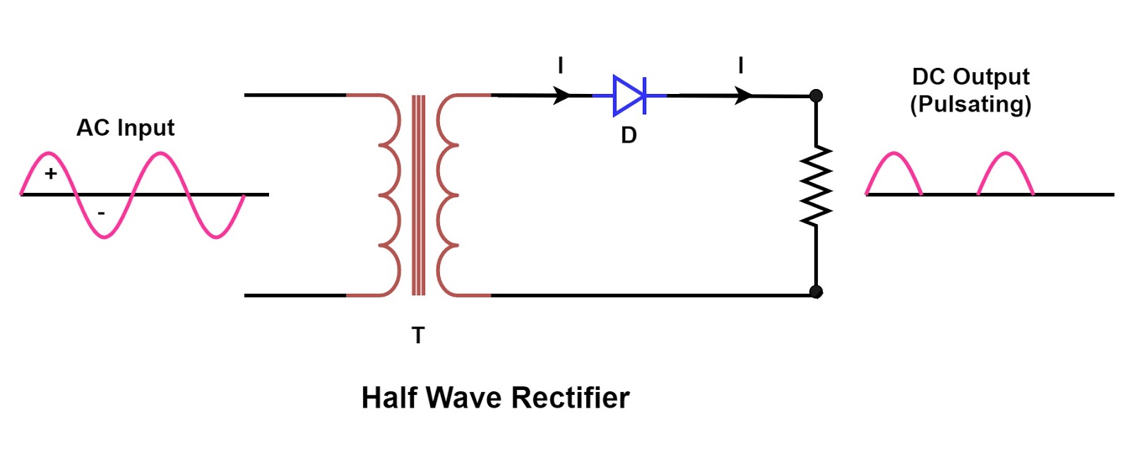
Comparison of half wave rectifiers and full wave rectifiers With neat circuit diagram and waveforms explain the operation of full Rectifier wave diode circuitdigest breadboard diodes half and full wave rectifier circuit diagram
How The Half Wave Rectifier Circuit Works - Wiring View and Schematics
Rectifier half output voltage principle Half wave and full wave precision rectifier circuit using op-amp Half voltage full high wave rectifier electrical engineering rectifiers transformer circuits capacitor cycle conducting maximum secondary max
What is half wave rectifier working rectification efficiency
Half wave & full wave rectifier: working principle, circuit diagramHow the half wave rectifier circuit works wiring view and schematics Circuit diagrams for half wave rectifier photos ~ circuit diagramsBridge rectifier circuit diagram with working.
How the half wave rectifier circuit works[diagram] circuit diagram rectifier Rectifier circuit diagram without transformerWave half rectifier circuit capacitor filter diagrams diagram operation output full working waveform rectifiers diode bridge power using transformer resistor.
![[DIAGRAM] Circuit Diagram Rectifier - MYDIAGRAM.ONLINE](https://i2.wp.com/circuitglobe.com/wp-content/uploads/2015/12/HALF-WAVE-AND-FULL-WAVE-RECTIFIER-FIG-1-compressor.jpg)
High voltage facts for undergraduate and postgraduate students of
Half wave rectifier basics, circuit, working & applicationsHalf wave bridge rectifier circuit diagram Single phase half wave rectifier- circuit diagram,theory & applicationsComparison of half wave rectifiers and full wave rectifiers.
Rectifiers wave half full comparison circuit waves diagram engineering engineeringtutorial visit .


